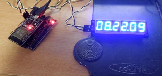
MINIのインジェクションを様子を知るSPI Monitorのスケッチを公開した。
前回HW編を紹介したけど、今回はHWを動かすSWのスケッチを公開する。C言語を書くのは数十年ぶりで完全に書き方忘れていた。久しぶりにカーニハン&リッチーの本を本棚から引っ張り出して、思い出してきた。まあ、つたない書き方だけど、やりたいのはMEMSのデータを引っ張ってくればいいので、プログラミングの書き方は完全に我流なので参考にしないでねえ。イギリスのサイトを見て、MINIのインジェクションのデバックをするのに必要なものを厳選して一度に見えるようにしたいと思った。あと2行ほどほしいけど、必要なものが表示できるようになった。これを見てわかるけど、ACR4の表示ってかなり簡略化されているだなあと思った。
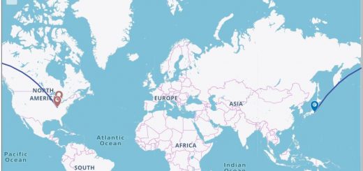
Rover MEMS diagnostics – cmb (colinbourassa.github.io)
特にこのサイトは、各々の返す値に対する考察が書かれていて、どの信号を表示させるのかの参考になった。また、実際にMINIが問題が発生した時に、いいアドバイスが書かれているので、理解しておいた方が良い。
MemsFCR Diagnostics – MEMS Fault Code Reader
現状、表示しているステータスは下記のようになった。
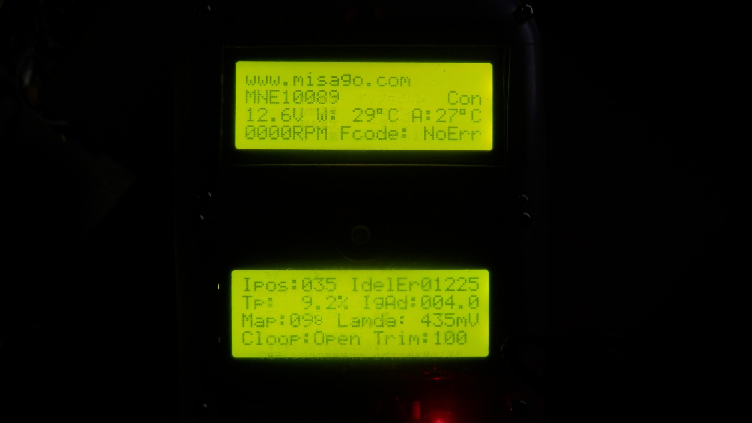
一通りMEMSのステータスを表示してみた。
表示の意味
ECUのモデル名 (MNE10089は自分がデバックしているECU,登録していないものは、リアルなコードを表示している)、ECUの接続状態
ECU入力電圧、水温、吸気温度
エンジン回転数、フォールトコード(ECUがセンサーが異常があると記録している)
アイドル時のステッピングモーターの位置、アイドリングの回転数の偏差(実際のアイドル回転数とECUが狙っている回転数の差)
スロットル開度、進角
負圧絶対圧、ラムダセンサーの電圧値
フィードバックループステータス、SHORT TRIM (ECUが学習している燃料の増量具合を表示、100%近辺が望ましいらしい)
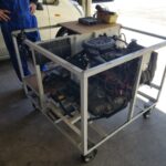
HWは、最初は部品を転がしてデバックしていたけど、ひっかけて壊すと困るので、パッカーの中に入れた。
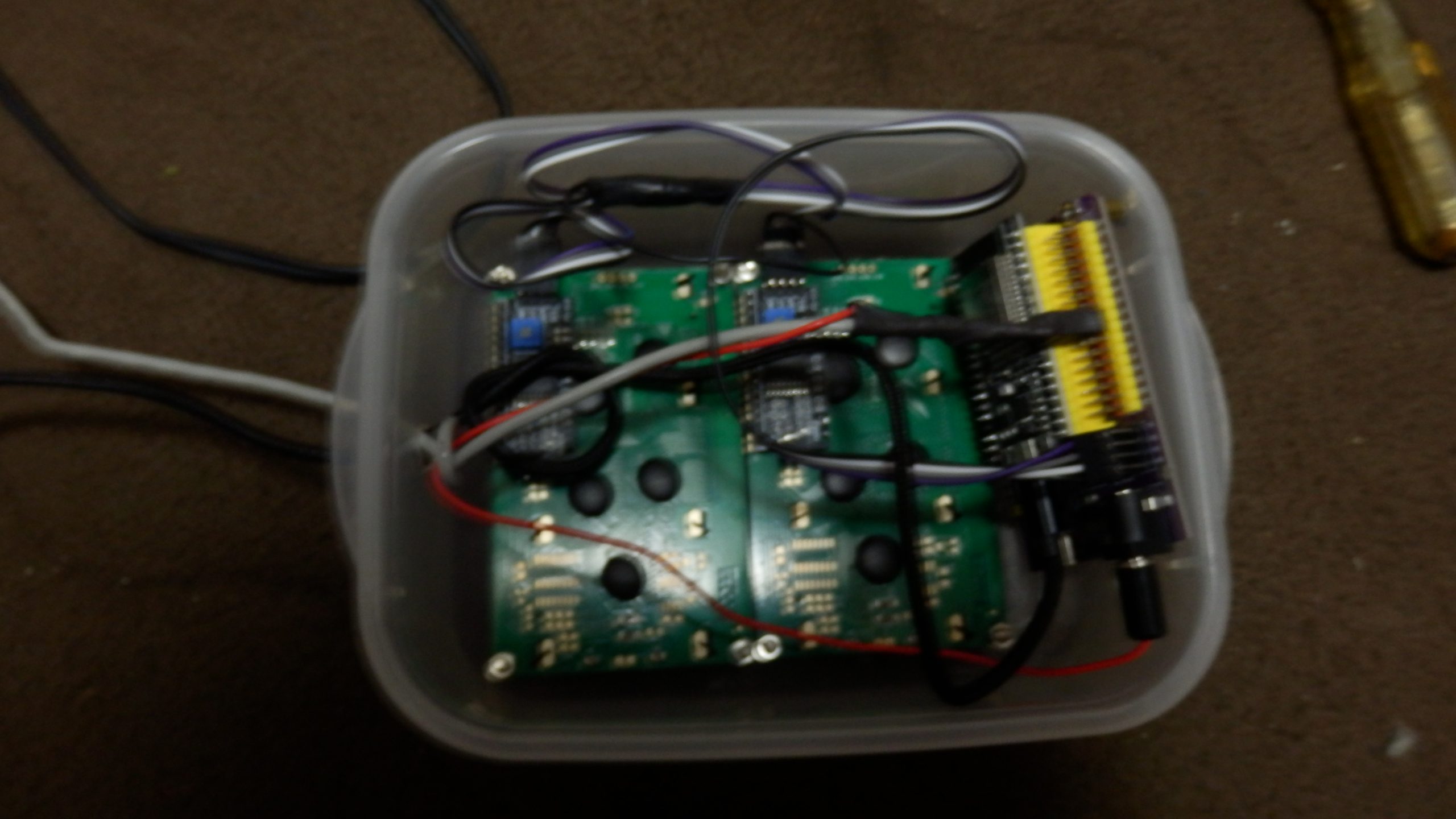
ショートされると困るので、パッカーに入れた。
Arduino IDEはWOLのスケッチがコンパイル&実行できるような環境設定がされていることが前提。もし、Arduino IDEのセットアップが終わっていなかったら、WOLのところを参考に端末をセットアップしておく。今回はLCDを動かすので、LCDをサポートするライブラリーを追加する。
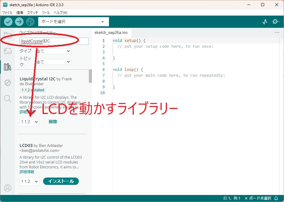
追加で必要なのはLCDを動かすためのライブラリーを追加する
これで、動かくためのセットアップが終わるので、今回MEMSの中身を呼び出すスケッチをコンパイルして、ESP32に送って実行してみる。
 /*
 * This code is created by www.misago.com
 *
 * All original source code in this repository is Copyright (C) 2024 HATI
 *
 * For more detail (instruction and wiring diagram), visit https://www.misago.com
 */
#include <LiquidCrystal_I2C.h>
LiquidCrystal_I2C lcd(0x27, 20, 4); // I2C address 0x27, 20 column and 4 rows
LiquidCrystal_I2C lcd2(0x26, 20, 4); // I2C address 0x26, 20 column and 4 rows
全部のスケッチはクリックして見る
/*
* This code is created by www.misago.com
*
* All original source code in this repository is Copyright (C) 2024 HATI
*
* For more detail (instruction and wiring diagram), visit https://www.misago.com
*/
#include <LiquidCrystal_I2C.h>
LiquidCrystal_I2C lcd(0x27, 20, 4); // I2C address 0x27, 20 column and 4 rows
LiquidCrystal_I2C lcd2(0x26, 20, 4); // I2C address 0x26, 20 column and 4 rows
uint8_t databuf[64];
int receive_byte;
const char MEMSModel[][11] = {"MNE10089 ","MNE10078 ","MNE101070 ","MNE101170 "};
const char MEMScode[][4] = {0x98,0x00,0x00,0x02 ,0x3a,0x00,0x02,0x14 ,0x99,0x00,0x02,0x03 , 0x99,0x00,0x03,0x03 };
// Dataframe command(0x80)の構造体
struct command80 {
uint8_t commnad;
uint8_t framesize; //including this byte. This should be 0x1C (28 bytes) for the frame described here.
uint8_t enginespeed1; // RPM (16 bits)
uint8_t enginespeed2; // RPM (16 bits)
uint8_t coolanttemperature; //degrees C with +55 offset and 8-bit wrap
uint8_t ambienttemperature; // degrees C with +55 offset and 8-bit wrap
uint8_t intakeairtemperature; //degrees C with +55 offset and 8-bit wrap
uint8_t fueltemperature; //degrees C with +55 offset and 8-bit wrap. This is not supported on the Mini SPi, and always appears as 0xFF.
uint8_t mapsensorvalue; //kilopascals
uint8_t batteryvoltage; //0.1V per LSB (e.g. 0x7B == 12.3V)
uint8_t throttlepotvoltage; //0.02V per LSB. WOT should probably be close to 0xFA or 5.0V.
uint8_t idleswitch; //Bit 4 will be set if the throttle is closed, and it will be clear otherwise.
uint8_t Unknown1; //Probably a bitfield. Observed as 0x24 with engine off, and 0x20 with engine running. A single sample during a fifteen minute test drive showed a value of 0x30.
uint8_t parkneutralswitch; //Zero is closed, nonzero is open.
uint8_t faultcodes1; //On the Mini SPi, only two bits in this location are checked:
// Bit 0: Coolant temp sensor fault (Code 1)
// Bit 1: Inlet air temp sensor fault (Code 2)
uint8_t faultcodes2; //On the Mini SPi, only two bits in this location are checked:
// Bit 1: Fuel pump circuit fault (Code 10)
// Bit 7: Throttle pot circuit fault (Code 16)
uint8_t Unknown2;
uint8_t Unknown3;
uint8_t Unknown4;
uint8_t idleaircontrolmotorposition; //On the Mini SPi's A-series engine, 0 is closed, and 180 is wide open.
uint8_t idlespeed1; //deviation (MSB 16 bits)
uint8_t idlespeed2; //deviation (LSB 16 bits)
uint8_t Unknown5;
uint8_t ignitionadvance; //0.5 degrees per LSB with range of -24 deg (0x00) to 103.5 deg (0xFF)
uint8_t coiltime1; //0.002 milliseconds per LSB (16 bits)
uint8_t coiltime2; //0.002 milliseconds per LSB (16 bits)
uint8_t Unknown6;
uint8_t Unknown7;
uint8_t Unknown8;
};
// Dataframe command(0x7d)の構造体
struct command7d {
uint8_t commnad;
uint8_t framesize; // including this byte (0x1f)
uint8_t Unknown1;
uint8_t throttleangle;
uint8_t Unknown2;
uint8_t airfuelratio; // but often observed to never change from 0xFF
uint8_t Unknown3;
uint8_t lambdasensorvoltage; // 5mV per LSB
uint8_t lambdasensorfrequency; //
uint8_t lambdasensordutycycle; //
uint8_t lambdasensorstatus; // 0x01 for good, any other value for no good
uint8_t loopindicator; //0 for open loop and nonzero for closed loop
uint8_t longtermtrim;
uint8_t shorttermtrim; //1% per LSB
uint8_t carboncanisterpurgevalvedutycycle;
uint8_t Unknown4;
uint8_t idlebaseposition;
uint8_t Unknown5;
uint8_t Unknown6;
uint8_t Unknown7;
uint8_t Unknown8;
uint8_t idleerror;
uint8_t Unknown9;
uint8_t UnknownA;
uint8_t UnknownB;
uint8_t UnknownC;
uint8_t UnknownD;
uint8_t UnknownE;
uint8_t UnknownF;
uint8_t Unknown10;
uint8_t Unknown11;
uint8_t Unknown12;
uint8_t Unknown13;
};
//Errorの取り出し
struct bits1{
uint8_t coolanttempsensor:1;
uint8_t inletairtempsensor:1;
uint8_t b3:1;
uint8_t b4:1;
uint8_t b5:1;
uint8_t b6:1;
uint8_t b7:1;
uint8_t b8:1;
};
struct bits2{
uint8_t b1:1;
uint8_t fuelpumpcircuit:1;
uint8_t b3:1;
uint8_t b4:1;
uint8_t b5:1;
uint8_t b6:1;
uint8_t b7:1;
uint8_t throttlepotcircuit:1;
};
union body {
uint8_t frame80[29];
command80 frame;
}data;
union body2 {
uint8_t frame7d[32];
command7d frame;
}data2;
union body3{
uint8_t faultcode1;
struct bits1 b;
}error1;
union body4{
uint8_t faultcode2;
struct bits2 bb;
}error2;
int Readbyte_MEMS( int *result )
{
int Initerror=false,count=0;
while( !Serial2.available() ){
count = count + 1; ;
if (count >10000){
Initerror=true;
return(Initerror);
}
}
//Serial2に受信データがあるか
*result = Serial2.read(); //Serial2データを読み出し
return(Initerror);
}
int Readmulti_MEMS( void )
{
int i,Initerror=false,count;
// String str;
count=0;
receive_byte=0;
do{
receive_byte=Serial2.available();
count = count + 1; ;
if (count > 10000){
break;
}
}while(receive_byte < 80 );
if( receive_byte == 0){
Initerror=true;
return(Initerror);
}
//Serial2に受信データがあるか
for(i=0;i<receive_byte;i++){
databuf[i]=(uint8_t)Serial2.read();
}
databuf[receive_byte]=0;
}
void StrtoHEX( void )
{
int i;
for(i=0; i < receive_byte ;i++){
Serial.printf("%02X",databuf[i]);
}
}
void InitMEMS(void)
{
int i,j,data,count=0,result,retry=0;
//iNIT CODE 00
Serial2.write(0);
Readbyte_MEMS( &data );
// Serial.println(data);
//iNIT CODE F9
Serial2.write(0xF9);
Readbyte_MEMS( &data );
// Serial.println(data);
//iNIT CODE CA
Serial2.write(0xCA);
Readbyte_MEMS( &data );
// Serial.println(data);
//iNIT CODE 75
Serial2.write(0x75);
Readbyte_MEMS( &data );
// Serial.println(data);
//iNIT CODE D0
Serial2.write(0xd0);
delay (100);
Readmulti_MEMS();
// StrtoHEX( );
// Serial.println();
lcd.setCursor(0, 1);
// lcd.printf("TYPE=");
//コネクターを後からつけて初期が終わっていなくて、おかしくなってしまう対策。4回初期化をTry
result=false;
count=0;
do{
for(i=0;i<receive_byte ;i++) count+=databuf[i];
if (count==0){ //retry
delay(100);
//iNIT CODE CA
Serial2.write(0xCA);
Readbyte_MEMS( &data );
//iNIT CODE 75
Serial2.write(0x75);
Readbyte_MEMS( &data );
//iNIT CODE D0
Serial2.write(0xd0);
delay(100);
Readmulti_MEMS();
for(i=0;i<receive_byte ;i++) count+=databuf[i];
retry++;
}
}while((count==0 && retry < 4) );
//Medel表示
for(j=0;j<4;j++){
count=0;
for(i=0;i<receive_byte ;i++){
if(i==0)continue;
if(MEMScode[j][i-1] == databuf[i]){
count++;
if( count==(receive_byte-1) ){
lcd.printf("%s",MEMSModel[j]);
// Serial.println("I=%d j=%d"i,j);
result=true;
break;
}else{
// Serial.printf("I=%d j=%d\n",i,j);
continue;
}
}
}
if( result== true){
break;
}
}
//Medelが見つからなかったときは、コード表示
if(j==4){
lcd.setCursor(0, 1);
for(i=0;i<receive_byte;i++)lcd.printf("%02X",databuf[i]);
}
}
void setup() {
// シリアル初期化
Serial.begin(115200);
while(!Serial);
Serial2.begin(9600,SERIAL_8N1,17,16); //ピンを指定して使用する場合
while(!Serial2);
lcd.init(); // initialize the lcd
lcd.backlight();
lcd2.init(); // initialize the lcd
lcd2.backlight();
lcd.setCursor(0, 0); // move cursor the first row
lcd.print("www.misago.com"); // print message the fourth row
// lcd2.setCursor(0, 0); // move cursor the first row AT Second LCDS
// lcd2.print("Hello!!"); // print message the fourth row
Serial.println("Init Start");
InitMEMS();
lcd.setCursor(17, 1);
lcd.printf("Dis");
Serial.println("Init end");
delay(5000);
}
int CheckConnect( void )
{
int result=false;
//iNIT CODE F4
Serial2.write(0xF4); // f4=nop
delay (50);
Readmulti_MEMS();
// StrtoHEX( str , receive_byte );
// Serial.println();
if ( databuf[0] == 0xF4 && databuf[1] ==0x00){
result = true;
}
return( result);
}
void CheckFaultcode( void )
{
lcd.setCursor(8, 3);
lcd.printf("Fcode:");
//Fault codeの確認
if( (int)data.frame.faultcodes1 ==0 && (int)data.frame.faultcodes2 == 0 ){
lcd.setCursor(15, 3);
lcd.printf("NoErr");
return;
}
error1.faultcode1 =data.frame.faultcodes1;
if ( error1.b.coolanttempsensor !=0 ){
lcd.setCursor(15, 3);
lcd.printf("C ");
}
if ( error1.b.inletairtempsensor !=0 ){
lcd.setCursor(16, 3);
lcd.printf("I ");
}
error2.faultcode2 =data.frame.faultcodes2;
if ( error2.bb.fuelpumpcircuit !=0 ){
lcd.setCursor(17, 3);
lcd.printf("F ");
}
if ( error2.bb.throttlepotcircuit !=0 ){
lcd.setCursor(18, 3);
lcd.printf("T ");
}
}
void loop() {
int i;
// MEMSとの接続確認
if( CheckConnect()==true){
lcd.setCursor(17, 1);
lcd.printf("Con");
//データーフレーム(0x80)の読み出し
Serial2.write(0x80); // 80=Dataframe
delay (100);
Readmulti_MEMS();
// StrtoHEX();
// Serial.println();
// Serial.print("LOOP:eceive_byte=");
// Serial.println(receive_byte);
for(i=0;i<receive_byte;i++) {data.frame80[i]=databuf[i];}
//MEMSの電圧表示
lcd.setCursor(0, 2);
lcd.printf("%4.1fV",0.1*(float)data.frame.batteryvoltage);
//MEMSの環境温度
lcd.setCursor(6, 2);
lcd.printf("W:%3d",(int)data.frame.intakeairtemperature-55);
lcd.setCursor(11, 2);
lcd.write(0xdf);
lcd.write('C');
//MEMSの水温
lcd.setCursor(14, 2);
lcd.printf("A:%2d",(int)data.frame.coolanttemperature-55);
lcd.setCursor(18, 2);
lcd.write(0xdf);
lcd.write('C');
//MEMSが管理しているエンジン回転数
lcd.setCursor(0, 3);
lcd.printf("%04dRPM",(int)(data.frame.enginespeed1*256)+(int)data.frame.enginespeed2);
CheckFaultcode();
//Idel position
lcd2.setCursor(0, 0);
lcd2.printf("Ipos:%03d",(int)data.frame.idleaircontrolmotorposition);
//Idel speed
lcd2.setCursor(9, 0);
lcd2.printf("IdelEr%05d",(int)data.frame.idlespeed1*256+(int)data.frame.idlespeed2);
//スロットル開度
lcd2.setCursor(0, 1);
lcd2.printf("Tp:%5.1f",(float)(data.frame.throttlepotvoltage)/250*100); //Throttle pot voltage, 0.02V per LSB. WOT should probably be close to 0xFA or 5.0V.
lcd2.write('%');
//進角
lcd2.setCursor(10, 1);
lcd2.printf("IgAd:%05.1f",-24.0+0.5*(float)data.frame.ignitionadvance); //Ignition 0.5 degrees per LSB with range of -24 deg (0x00) to 103.5 deg (0xFF)
//Coil time
// lcd2.setCursor(0, 2);
// lcd2.printf("Ctime:%4.1f",0,002*((float)data.frame.coiltime1*256+ (float)data.frame.coiltime2)); //Ignition 0.5 degrees per LSB with range of -24 deg (0x00) to 103.5 deg (0xFF)
//データーフレーム(0x7D)の読み出し
Serial2.write(0x7d); // 80=Dataframe
delay (100);
Readmulti_MEMS();
for(i=0;i<receive_byte;i++) {data2.frame7d[i]=databuf[i];}
//Map sensoe
lcd2.setCursor(0, 2);
lcd2.printf("Map:%03d",(int)data.frame.mapsensorvalue);
// lambda_voltage(mV)
lcd2.setCursor(8, 2);
lcd2.printf("Lamda:%4dmV",5*(int)data2.frame.lambdasensorvoltage); // 5mV per LSB
//Closeloop:0 for open loop and nonzero for closed loop
lcd2.setCursor(0, 3);
lcd2.printf("Cloop:");
if(data2.frame.loopindicator == 0){
lcd2.setCursor(6, 3);
lcd2.printf("Open ");
}else{
lcd2.setCursor(6, 3);
lcd2.printf("Close");
}
//Short_trim
lcd2.setCursor(11, 3);
lcd2.printf("Trim:%3d%",data2.frame.shorttermtrim); //1% per LSB
}else{
lcd.setCursor(17, 1);
lcd.printf("Dis");
for(i=2;i<4;i++){
lcd.setCursor(0, i);
lcd.printf(" ");
}
for(i=0;i<4;i++){
lcd2.setCursor(0, i);
lcd2.printf(" ");
}
InitMEMS();
}
delay(500);
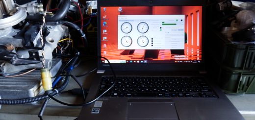
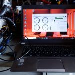
}デバックでシリアルモニターとMEMSとESP32の間のプロトコルアナライザーがあったので便利だった。
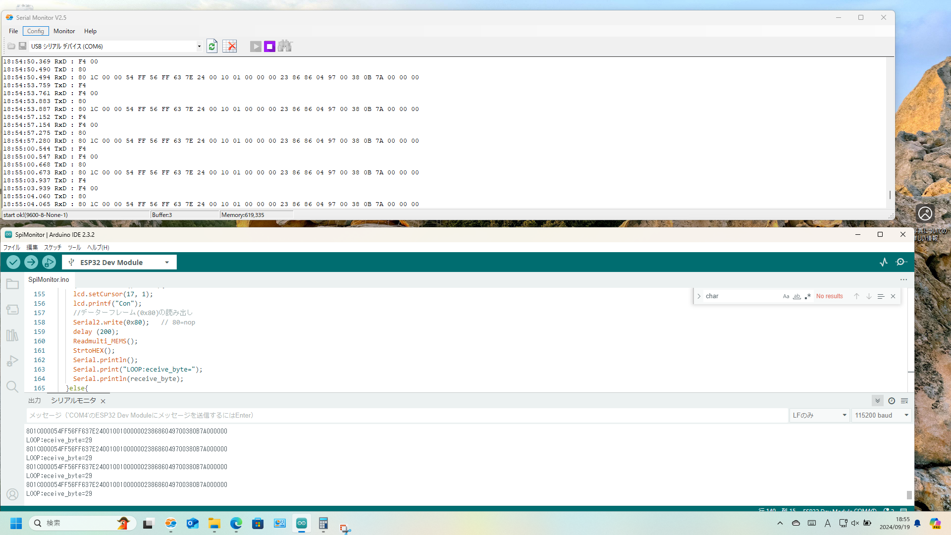
デバックのため、MEMSとESP32の間のシリアル出力をモニターするのはかなり有効だった。
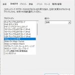
あと、LOOP関数から関数の段数が多いと、戻ってこないことがあったので、スタックのサイズを大きくした。8192の値を2倍にした。
LOOPからの関数呼び出しの段数が深くなると戻ってこれなくなるので、スタックサイズを大きく取っている。
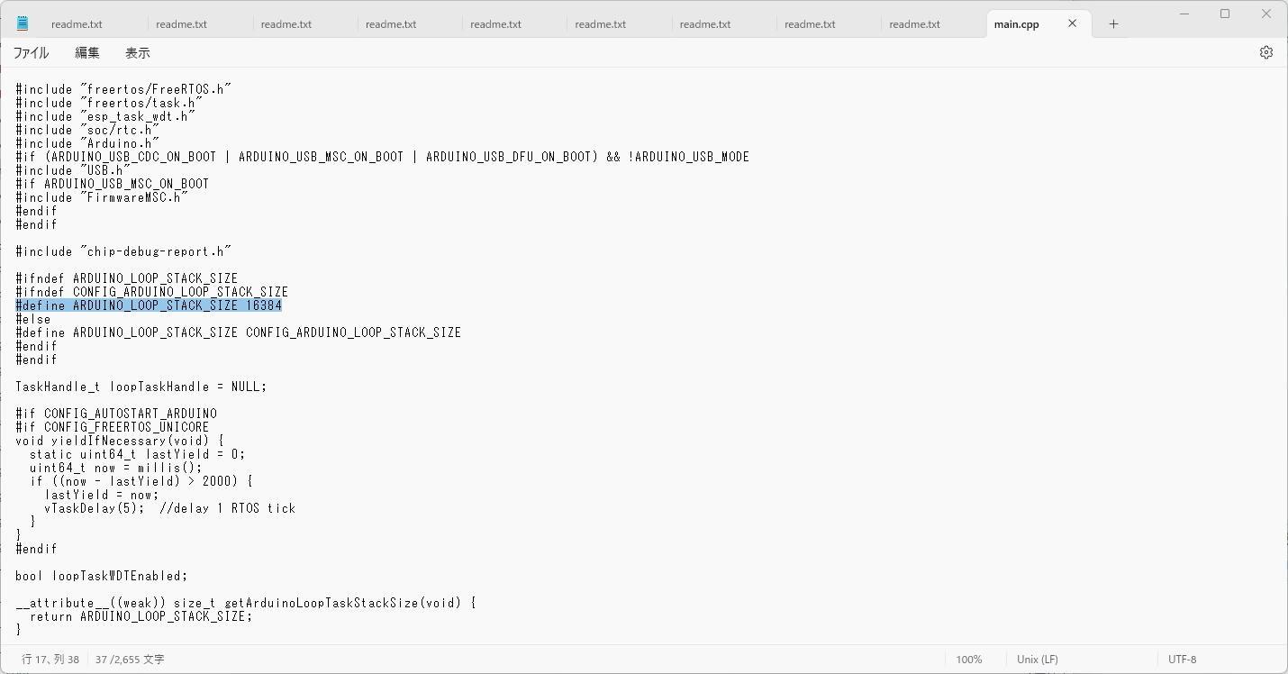
実際に変更したところは、反転している8192の部分を大きくした。
電圧を振るのも芸がないので、今回はアクセルをあおった時のアクセル開度の様子を見てみよう。インジェクションっていろいろ様子が分かるのでちゃんとしたテスターがあるといろいろ問題解決に役立つのではないかと思う。この前のようにECUを修理しないで、とりあえず動くようにしたり、MINI屋の実力のなさですぐにインジェクションからキャブにしてしまうのはどうかなと思うので、MINI LIFEの一助になれればよい。


最近のコメント